- Published on
- Spring 2021
Variable Light Box
A compact box containing a light that can be switched between continuous and blinking modes and can be modulated in brightness
Role
Engineering Lead
Skills Used
- CAD in OnShape
- Circuitry
- PCB design in KiCad
Collaborators
none
Background
In Medical Device Design I, I was tasked with creating a box containing a variable light. I used the engineering design process starting from mapping user needs to specifications all the way to testing and verification.
Links
Key Features
- A light with a continuous and blinking mode, controlled by a switch
- A rotary knob to modulate brightness in both modes
- An on/off switch
- An easily replaceable battery with a life of > 4 hours
- A portable, durable, safe enclosure
- An affordable design
User Needs


CAD Design
Enclosure Design
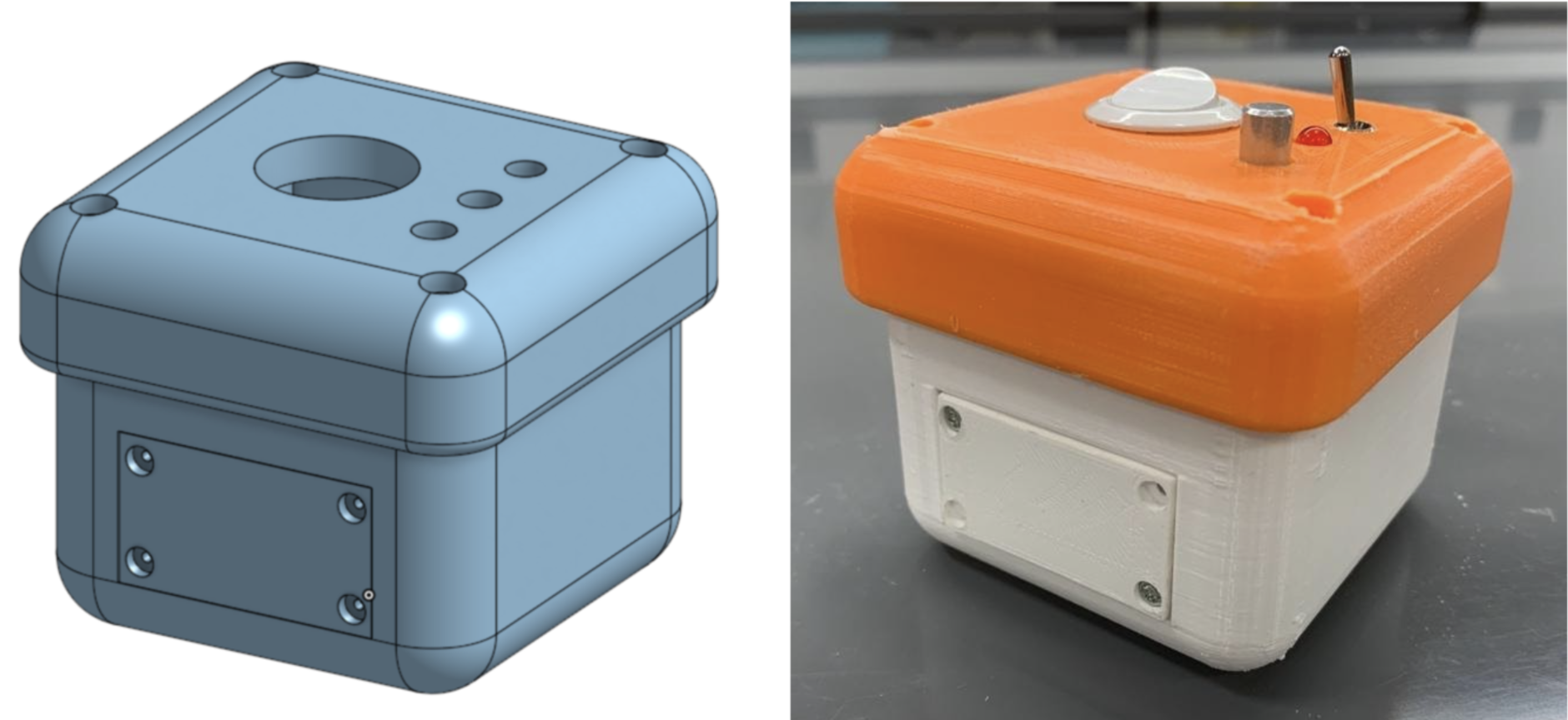
CAD and real isometric views of full assembly
Top and exploded views of full assembly
1 of 2


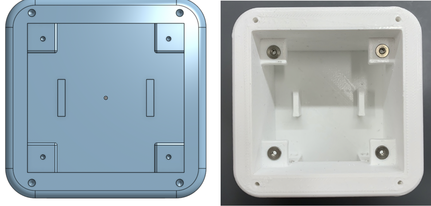
Base
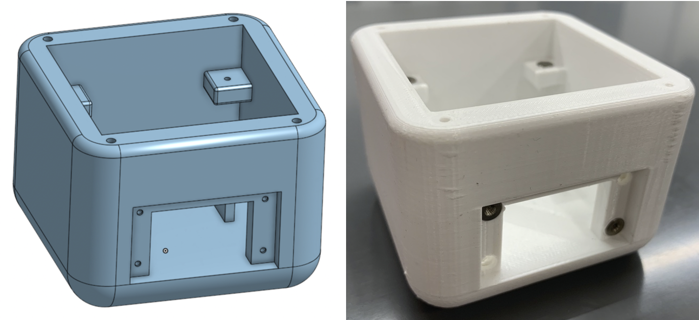
CAD and real isometric views of base
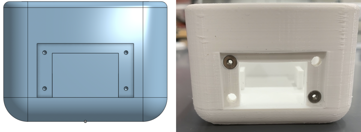
CAD and real front views of base
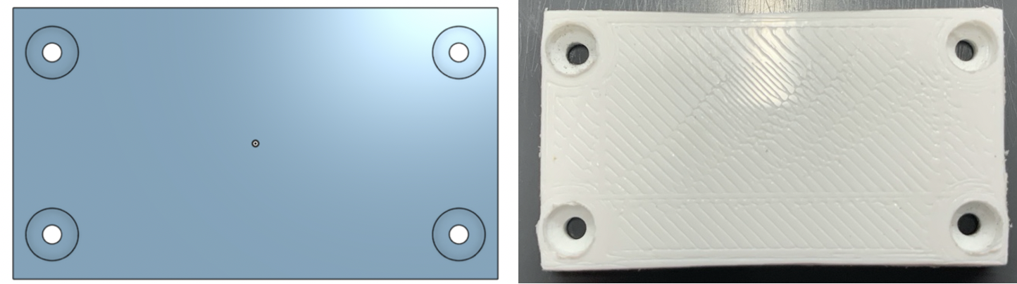
CAD and real top views of base
1 of 3


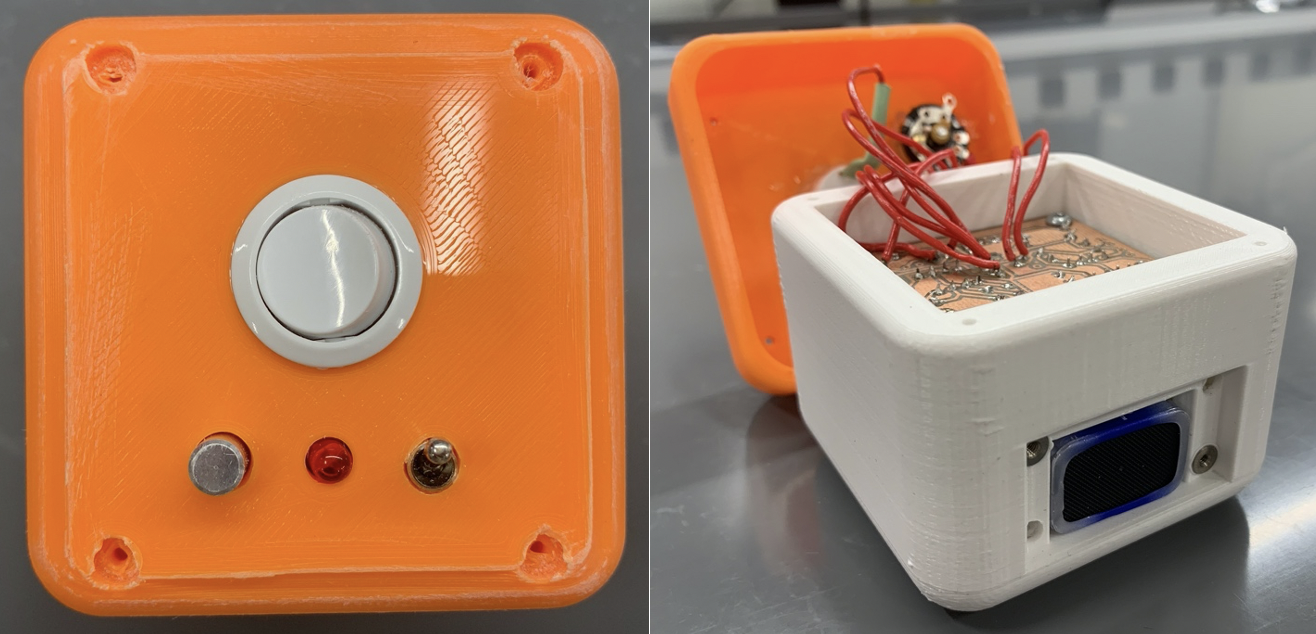
Lid
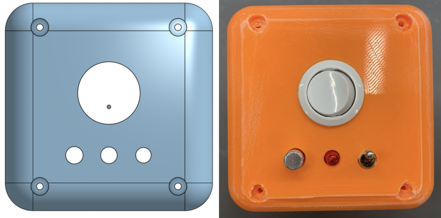
CAD and real top views of lid
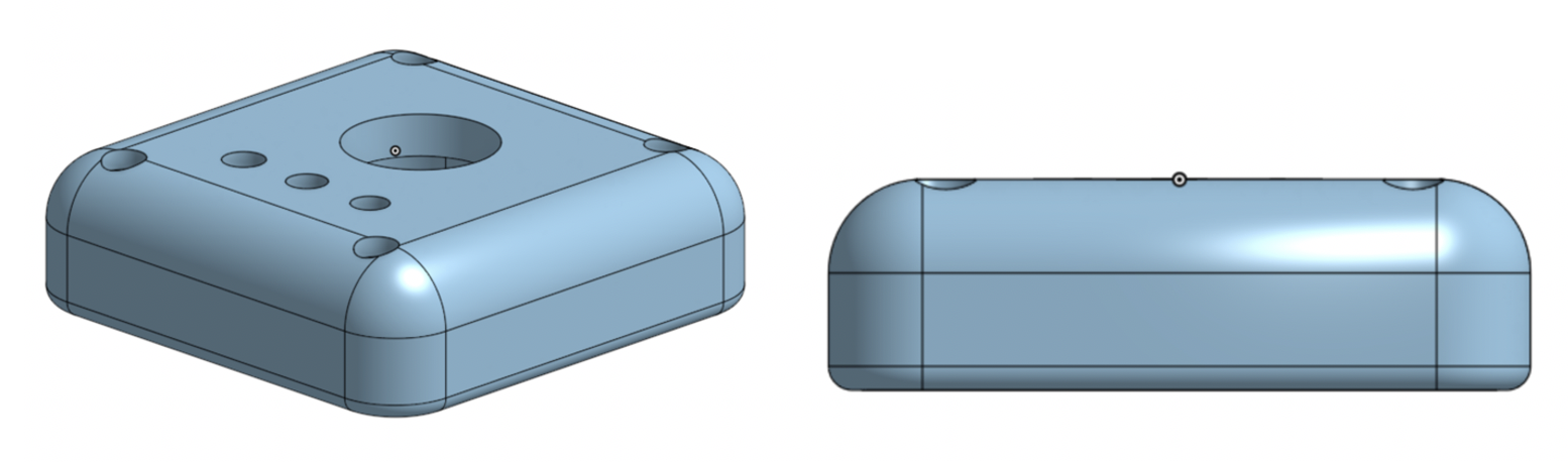
CAD isometric and sides views of lid
1 of 2


Battery Lid
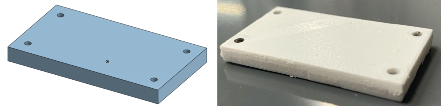
CAD and real isometric views of lid
CAD and real side views of battery lid
1 of 2

Electronics Design
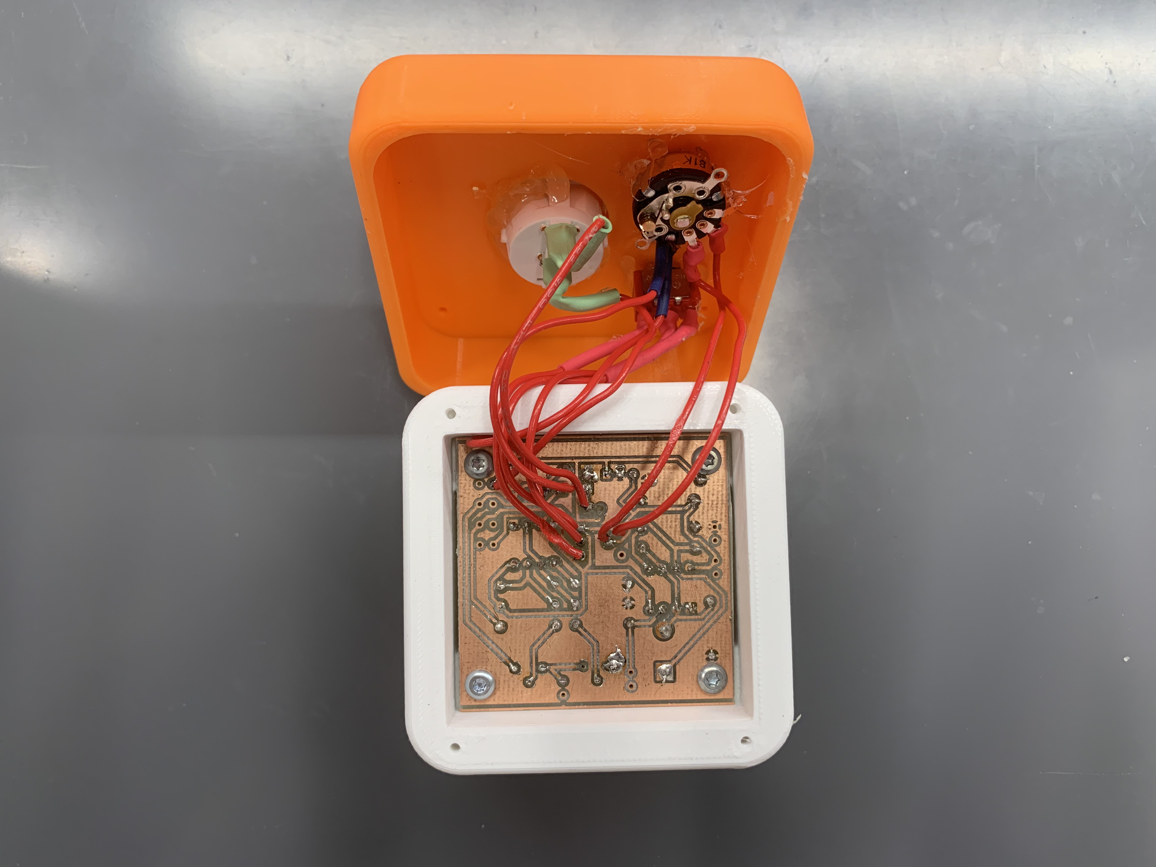
PCB in enclosure
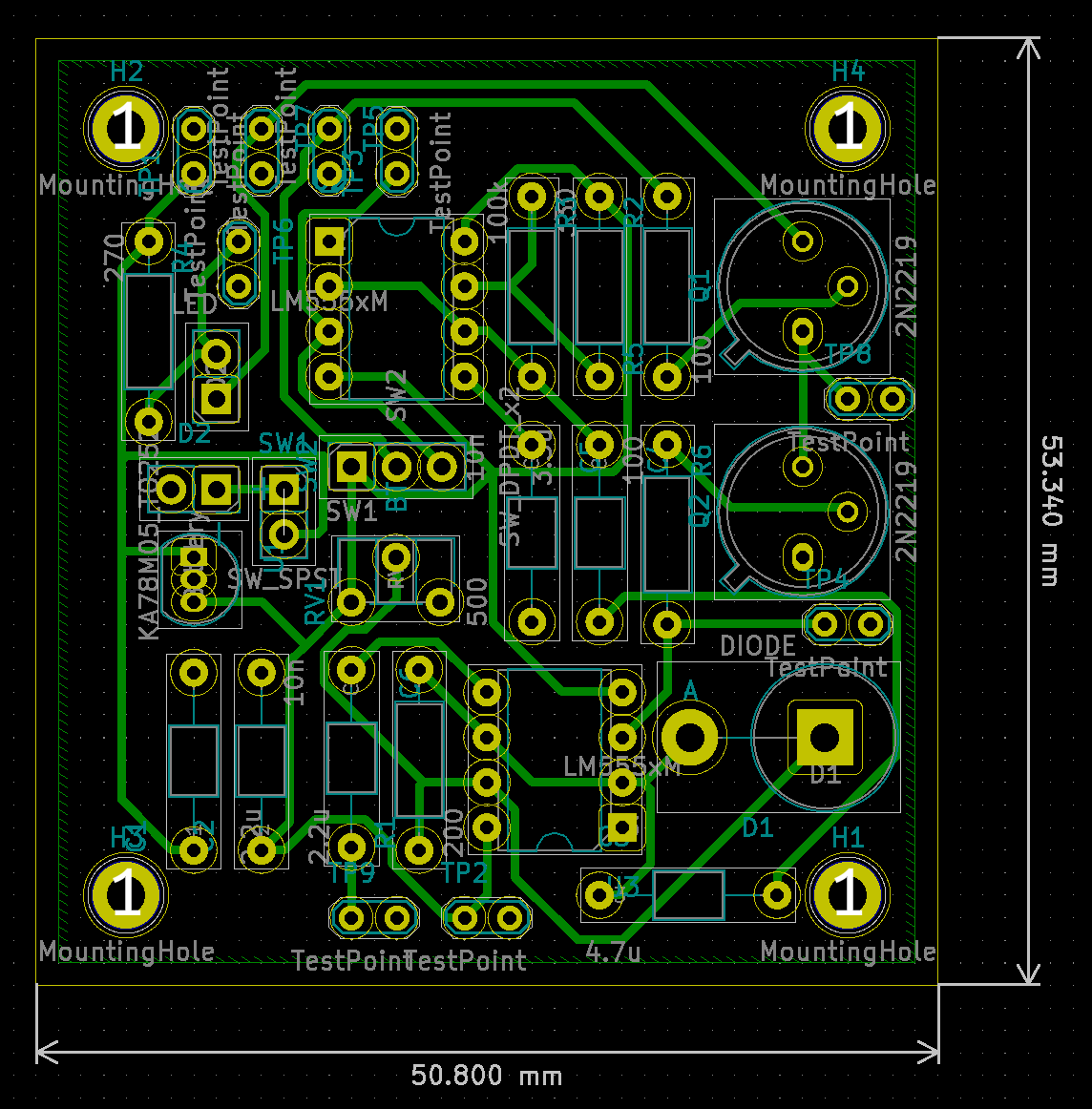
PCB generated in KiCAD
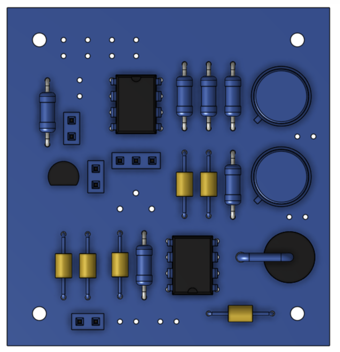
CAD view of PCB
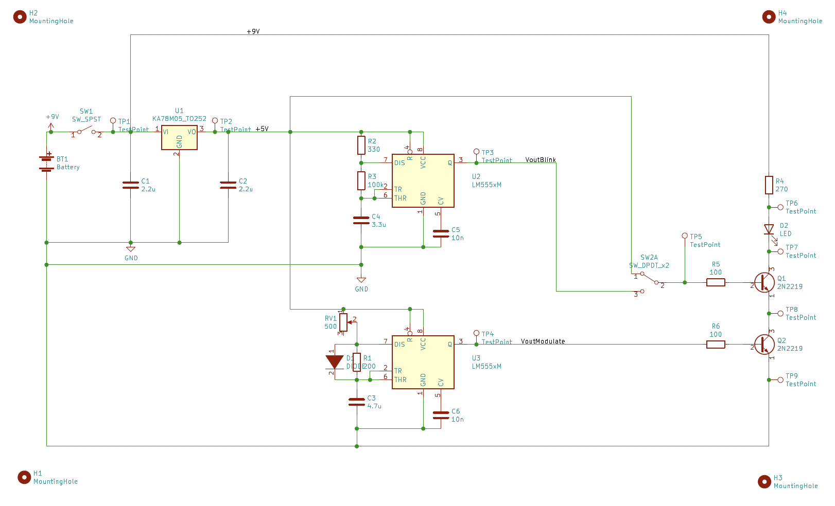
Circuit Schematic
1 of 4
Testing
Light Functionality


Battery Design


Box Design


Light Functionality Testing Details
-
To test for brightness modulation, an oscilloscope was used to measure voltage across the resistor directly preceding the LED at minimum and maximum brightness levels because voltage is proportional to current, which is proportional to current. The mean minimum voltage was found to be 0.0 ± 0.0 V, while the mean maximum voltage was found to be 5.424 ± 0.003 V. A two-tail one-sample t-test was conducted to compare the voltages between the minimum and maximum brightness settings. The null hypothesis was that there is no difference between the minimum and maximum voltages. The t-test gave a p-value of 6.403E-14, which is less than 0.001, so the null hypothesis is rejected. This indicates that the two sets of data are statistically different, so the rotary knob significantly modulates the brightness of the LED.
-
To test if the potentiometer linearly modulates the brightness, the voltage was measured at various degrees of rotary knob rotation with an ammeter, and voltage versus knob rotation was plotted in Figure 6a below. It is important to note that the ammeter gave different maximum voltage value than the oscilloscope, likely due to tolerance levels. The voltage to rotation relationship appears relatively linear but makes a very large from 0V at 0 degrees to 3.08V at 30 degrees. The R2 value for the linear line of best fit is 0.7197, which is not very high and suggests that the knob does not perfectly linearly modulate the brightness of the LED. However, to the eye, the brightness does appear to increase as the knob continues to rotate, despite the relationship not being linear. Therefore, this test is considered “passed.”


- To test if the light blinks at a 2Hz frequency, the number of blinks in 10 seconds was counted, giving a mean value of 1.980 ± 0.039Hz. To test the duty cycle, the oscilloscope was used to measure the time between timer blinks at the output of the DPDT switch, which gave a mean value of 48.788 ± 0.312%. Both of these values with their 95% confidence intervals were within the marginal values, sot the test was considered passed. Images of 555 timer outputs for the blinking and brightness modulation circuits can be seen in Figure 6b below.


- To test if the maximum brightness is the same in continuous and blinking modes, an oscilloscope was used to measure the voltage across the resistor directly preceding the LED for both light modes. The mean continuous voltage was found to be 5.424 ± 0.003V, while the mean blinking voltage was found to be 5.425 ± 0.004V. A two-tail one-sample t-test was conducted to compare the voltages for blinking and continuous modes. The null hypothesis was that there is no difference between the maximum brightness continuous and blinking mode voltages. The t-test gave a p-value of 0.374, which is greater than 0.05, so the null hypothesis is accepted. This indicates that the two sets of data are not statistically different, indicating the maximum brightness is equivalent in both light modes.
Battery Design Testing Details
-
To test if the battery is replaceable in under 5 minutes, battery replacement was timed, giving a value of 1.515 ± 0.191 minutes. The 95% confidence interval of this value is within the marginal value, so the test was passed.
-
To test battery life, 9V of power was connected to the circuit using a power supply, and the amount of current drawn was recorded from the power supply for both continuous and blinking light modes at maximum brightness. The battery's current output, 500 mAh, was divided by the recorded current to calculate the number of hours to battery depletion. Blinking mode gave a value of 6.494 ± 8.7E-16 hours, while continuous mode gave a value of 4.817 ± 0.0339 hours. Since both 95% confidence intervals of these values are within the marginal value, the test was passed.
-
In order to calculate which three items draw the most power in the circuit, the voltage drop was measured across several components, and the power was then calculated using Watt's law, P=IV, using literature and datasheet values for current. Power across six different components is listed in Table 3a below. The three components that draw the most power are the 270Ohm resistor preceding the LED, the LED itself, and the voltage regulator, highlighted in orange.


Box Design Testing Details
-
To test the weight of the unit, the entire box with all internal and external components was placed on a scale. The value was found to be 0.380 lbs, which meets the ≤ 0.5 lbs requirement.
-
To test the dimensions of the enclosure, calipers were used to measure the largest length, width, and height. The box was found to be 3x3x2.616 in, which all satisfy the ≤ 3 in requirement.
-
To calculate the price of the unit, all components were compiled into a spreadsheet, and individual component prices were found online. These values are listed in Table 4a below. The total price was calculated as $12.83, which meets the ≤ $20 requirement.


Final Product
Light Box Construction
Functional Interface
Breadboard Demonstration
Battery Replacement
Reflection
This project was writhe with success and failures in the CAD design, printed circuit board design, and full assembly construction. On a high note, the circuit initially worked perfectly in the box enclosure until one wire disconnected and the circuit shorted. Consequently, all testing was performed on the breadboard, which worked as intended and passed all tests with confidence intervals well within the marginal values. Therefore, the circuit can be considered generally successful. Moreover, the printed circuit board is very neat, efficiently packing many different components into a small space. The soldering on the PCB, despite its small size, was also very neat and required little revision. Due to the small PCB size, the enclosure is able to have very thick and sturdy walls that can survive a drop test and protect the inner contents. This is also amplified by the smooth filleted edges around the entire box. The entire box is very compact, portable, and durable. The user interface is also neat, with the two switches, the knob, and the LED secured on the lid and protruding as little as possible.
However, there were some failures due to poor assumptions and fabrication errors that could be overcome in the future with a revised design. The PCB stopped functioning after working perfectly for several days, a result of one of the wires attached to an outside component coming out of the board while the 9V battery was plugged in, causing the 555 timer on the board to short, which resulted in several downstream errors and ultimately the failure of the board. This could have been avoided through several measures, one of which is using a power supply with a low maximum current setting to power the board instead of a 9V battery. Another preventative measure could have been to create an enclosure that had more room for connections to outside components. Since there is not much room above the PCB and the lid therefore sits relatively close to the PCB, the wires that connect the outside components to the PCB are pressed against the lid and are more likely to break or rip out of the board/components. A third option to prevent wires from breaking would be to house the outside components on an immobile part of the box, rather than the lid, which lifts up and down in order to access the PCB. Redesigning the base of the box with holes to fit the outside components would prevent the possibility of breaking wires when lifting the lid to access the PCB. Additionally, using heat shrink for all outside components would prevent shorting and would prevents connections from breaking as much. Another option to prevent shorting could be to use a TO-220 voltage regulator with a heatsink instead of a TO-92 because the circuit may draw too much current and cause the TO-92 to become very hot.
Despite many challenges, this project was a multifaceted effort, teaching me new skills along the way. Designing precise tolerances and watching the parts come together from the 3D printer was nerve wracking and fulfilling. When the enclosure was fully assembled and powered on, it felt pretty cool to know that I had designed every piece of this system. I'd like to thank my instructors and TAs for sharing their knowledge and honing mine and my classmates' skills throughout this semester. I'm confident we'll continue to leverage and grow these skills to design, test, and build the products of the future.